madison doucette
engineering design project
check out some of my formal engineering projects, as well as solo, explorative endeavors


quicker disconnect, jr.
a smaller, safer, and savvier way to connect pediatric AFOs to twister cables

this project was in collaboration with the Shirley Ryan AbilityLab and client Elyse Zanghi. we created a device to connect twister cables to ankle-foot orthotics (AFOs) in a safe, efficient manner that fit the size constraints of a pediatric patient.
in this project, we employed a spring button system, commonly found in crutches, within a lightweight aluminum box. this design allows for easy connection/disconnection while meeting strength requirements due to a tight internal fit.
project requirements + rationale
safety
rounded edges and child-safe materials based on use by children with minimal muscular control due to conditions such as CP or muscular dystrophy
strength
support the force of 70 lbs of torsion based on the calculated moment created by the application of the weight of a 7 year old of the 95th percentile (upper age and weight limit)
size
within the dimensions of 3" x 1" x 3/4" based on the dimensions of the existing solution (4 7/8"x 1 1/8"x 1/2") and the clients specification of minimal lateral protrusion from the leg
ease of connection
connection/disconnection in under 1 second based on matching or improving upon the speed associated with the existing product
initial mockups
below are four of our initial mockups presented to our client in a primary stage of user testing

carabiner
this mockup was based on the easy connection/disconnection requirement and the strength associated with rock climbing gear
we moved away from such a design due to inconsistency of the carabiner's locking mechanism when machined to our needs

buckle
this mockup was based on the easy connection/disconnection requirement, specifically with respect to the self-explanatory nature of attachment
we moved away from such a design due to an inability to meet strength requirements for both compression and tension

medicine-cap
this mockup was based on the easy connect/disconnection and child safety requirements as the child-lock mechanism similarly decreased the risk of a child's accidental detachment
we moved away from such a design due to problems with security and lateral protrusion

hinge
this mockup was based on the strength and child-safe material requirement as the metal casing was both strong and able to be efficiently cleaned
we progressed with this general concept of an enclosed attachment, but moved away with respect to an opening hinge
notable design features
below are our features that developed from alterations to the hinge mockups

spring button mechanism
our mode of connection and disconnection is dependent on a slotted, double spring button
rectangular metal tubing
the lightweight, aluminum component that is attached the AFO and allows for a secure fit


spacer + spring button system
the result of attaching the spring button to the twister cable attachment, using spacers for a secure fit
project takeaways + next steps
below are the conclusions with respect to learning and next steps
I gained skills in many manufacturing and prototyping processes such as:
metal working
milling + calibrations
performance testing
takeaway #1
this project could be developed upon by:
manufacturing the metal tubing itself to avoid the constraints of commercially available projects
finding a spring button of larger spring constant to increase durability and longevity
next steps
I gained knowledge of the design process geared towards a client:
client contact + interaction
user observation + testing
design documentation
takeaway #2
longboards
an independent design project to hone woodworking and manufacturing skills

this project was initiated based on self-interest and a desire to understand to process of manipulating wood to form a camber.
the deck of the boards were constructed in slightly different ways based on the style of board. such differences are outlined below in the "shaping rational + testing results" section.
iterations of boards
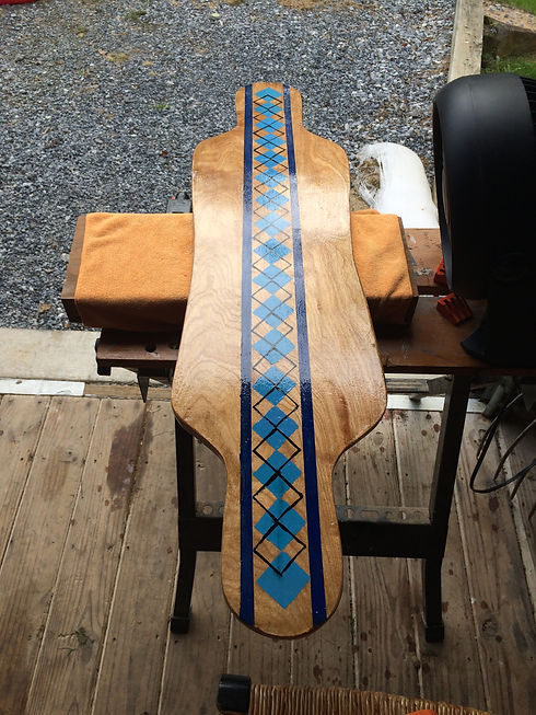
double kick cutaway
material: 3, 1/4" sections of plywood
method:
soaked in water for 3 hours
glued using Titebond + clamped
pressed to a frame made of 2x4s
shaped using a skill saw
refined curvature with a belt sander
camber: directed across both the horizontal and vertical axis of the board
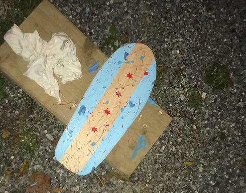
mini cruiser
material: 5, 1/8" sections of higher grade wood
method:
glued using Titebond + clamped
pressed to form a kick tail
shaped using a skill saw
refined curvature with a belt sander
camber: kick tail on the back 25% of the board without variation along horizontal axis
shaping rationale + testing results
shaping: double kick cutaway
the shape was chosen to be adaptable as a commuter board. based on the cut-outs around the wheels, the trucks can be loosened to decrease turning radius without making contact with the deck surface.
shaping: mini cruiser
the shape of this board was chosen to minimize size while maintain stability. the board is as wide as the double kick cutaway, but less than half the length, making it easier to maneuver in tighter spaces.
performance: double kick cutaway
this board performed as expected with respect to turning due to the cut-outs. overall, the board was rideable, before becoming cracked, for 1.5 years of daily commuting use. overtime, the lower fidelity of the wood became apparent due to a decreased stiffness.
performance: mini cruiser
the board performed slightly worse than expected. due to insufficient use of clamps, slight gapping occurred between the planes, changing overall deck height. while still rideable and maneuverable, the board would lack long term with respect to durability due to the gaps.
hardware
below is the hardware used to make the decks rideable
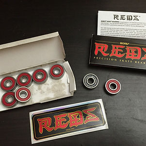
bearings
I used Bones Reds skateboard bearings due to their removable rubber face that allows for maintenance/cleaning and the longevity associated with pre-lubrication

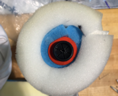
wheels
I used Hawgs Mini Monster 70mm 82a wheels because the size caters to maintained speed over acceleration and the central hardness on the spectrum comparing grip to drag

trucks
I used Paris 180mm 50 degree trucks because the width pairs nicely with the upper-end deck width of 8" and has a 6 hole base plate for increased mounting options
project takeaways + next steps
below are the conclusions with respect to learning and next steps
I learned about the processing of forming a camber through soaking the wood and pressing the glued plies into a mold of desired arc
takeaway #1
this project could be improved by:
selecting a stronger wood
using a symmetrical stencil
using more clamps to maintain camber
next steps
I learned how to shape a board through the use of blocking space with a skill saw and refining the curvature with a hand belt-sander
takeaway #2
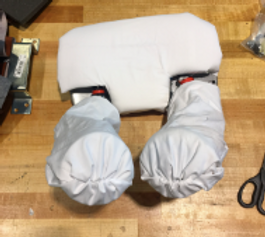
rest-up headrest
a safe and secure support against dystonia in TBI patients

this project was in collaboration with the Shirley Ryan AbilityLab and client Ashley Grebe. we were tasked with making a device to support patients with sustained traumatic brain injuries (TBIs) and are experiencing cervical dystonia.
to combat the potential for multiple directions of pull, we used a multi-faceted approach to support the head:
1. two malleable arms to support the chin
2. a head piece to prevent the pull's initiation
project requirements
adjustability
caters to multiple patients and can be adjusted by family members based on the expectation that a typical user's headrest needs to be adjusted 3 times per every 1.5 weeks
strength
supports the force of dystonia in multiple planes of motion based on overestimating the weight of the average adult human head to the 95th percentile (12 lbs)
maintainability
can be cleaned by the products used by the SRAL based on the current use of Sani-Cloth Bleach (.63% Sodium Hypochlorite) and Oxivir 1 (.5% Hydrogen Peroxide)
comfort
prevents against skin abrasions and unnecessary pressures based on observing user discomfort and friction against the headrest at user observation
notable design features
below are the notable features that developed from our flap mockup
cross-sectional layered padding
arms feature 3 layers of padding: an inner foam tube, a layer of memory foam, and an outer, softer foam
detachable from head piece
our design allows for the removal of the over arching forehead support when not necessary for certain patients

adjustable forehead support
hinged forehead pad allows for the angle to be changed, or entirely removed from the patient's face (image prior to fabric covering)
project takeaways + next steps
below are the conclusions with respect to learning and next steps
I gained skills in working with patients directly, as well as engaging with family members when necessary, to find ways to meet their needs apart from what was perceived by the client herself
takeaway #1
this project could be developed upon by:
using a metal wire of higher stiffness to increase applied support
secure padding directly around the overarching bar or contour the bar to prevent injury to those adjusting the headrest
next steps
I gained experience in material research due to the detail-oriented process of our selecting the proper foams/paddings for layering that met both comfort and support